3 Amps @ 30 VDC Resistive Non-Coded
2 Amps @ 30 VDC Resistive Coded
.9 Amps @ 125 VAC Resistive Non Coded
This is letting us know that if we need to switch a 30 volt DC (Direct Current) circuit through this relay, we must be below 3 amps (for Non-Coded) and 2 amps for (Coded).
There are two ways to find out if we are below this number.
#1) Read the data sheets and instruction manuals of the equipment that is being powered by this circuit. These informational sheets should have the current load numbers for your use. Add this number up by the quantity of equipment to be powered and you should have a number close to reality. I do not recommend this as you may end up calculating a number lower than actuality therefor jeopardizing the fire alarm relay.
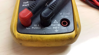
#2) With the proper use of a Multi Meter we can get an exact current reading from any circuit (as long as it is energized). Now keep in mind that Multi Meters have limitations on the current that can read as well. For example the Multi Meter we are using for this example has a 10 A fused limit for reading AC/DC current. Read below to find out how to set your Multi Meter up for reading current.
Before we continue please know the difference between a series circuit and a parallel circuit. In order to measure the load or current of a fire alarm circuit, we must place the Multi Meter test leads in SERIES with the circuit to be read. This is very important as it is impossible to do otherwise. Also note that you will need to move the positive test lead to the Amp test lead port as shown in the pictures below:
This picture shows the Fluke 117 Multi Meter with the test leads in the normal position to meter for voltage, resistance, capacitance, etc.
This pictures shows the Fluke 117 Multi Meter with the positive test lead moved over to the Amp port. This is mandatory when checking a fire alarm circuit for current.
Now as we stated above you need to place the Multi Meter test leads in series with the circuit being read. For example: If you have a relay with one leg landed on the C (Common) terminal and the other leg landed on the NC (Normally Closed) terminal your circuit is complete and the equipment being controlled should be functional. If you pull the wire leg off of the Common terminal, the equipment should stop.
Before we connect the Multi Meter to the circuit we need to insure we have the meter on the correct setting. Be aware if you are reading an AC or DC circuit and select the appropriate setting as noted in our previous article discussing Multi Meter basics.
Now with the wire disconnected from the Common terminal, land your negative (black) test lead on the Multi Meter to that same terminal on the relay. Now we need to complete the circuit to get an accurate current reading. Land the positive (red) test lead on the multi meter to the wire leg you disconnected from the Common terminal. If done correctly the equipment should power back up and your Multi Meter will display the total current of that circuit.
Below are a couple of pictures showing how the Multi Meter test leads should be connected to the circuit to properly read for current. Please note that the circuit used in these pictures is an SLC connected to a Notifier NFS2-3030 branching off to five FCM-1 addressable control modules.
 |
| SLC Connection on Terminal Strip |
 |
| SLC On Terminal Strip with Negative Conductor Disconnected for Current Reading |
 |
| Meter probes to make continuity between terminal and disconnected wire |
 If this is not something you feel comfortable with, then Fluke has you covered. Below is a picture of a current reading clamp that they make for their Multi Meters. All you need to do is plug it into your Fluke Multi Meter and clamp the spring loaded clamp around one leg of the circuit. This way you do not need to disconnect any live circuits.
Also note that relays are not the only application where you might need to take a current reading on fire alarm circuits. Other example applications may include NAC (Notification Appliance Circuits), Door Holder circuits, Magnetic Door Locks, etc. Always remember that you need to verify that you are not over-loading the circuit based on the limitation set forth in the data sheets and instructions manuals.
This concept is no different that your house. If you plug too many electronics into electrical outlets on one 120 VAC circuit then you are going to pop the breaker. These limitations are put in place for the protection of the equipment as well as your personal safety.


No comments:
Post a Comment